# 9. 空间位置解算
把一个三维的东西变成了一维或者二维。
因此,行列式值为0,也代表这个变换是不可逆的,因为如果三维变成了二维,那么可以视为有一个维度被压缩了,并且是压缩成0了。所以经过了这个变换以后,再也找不到这个维度原来的信息,无法实施逆变换。
我们可以用相机标定算出的**内参**和**畸变系数**外加透视的数学模型去拟合这个过程,从而实现二维到三维的转变。故在还原前,需先进行[*相机标定*](https://blog.csdn.net/define9/article/details/119517585)。
|  |
| :------------------------------------: |
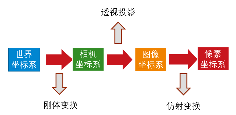
| *坐标系关系* |
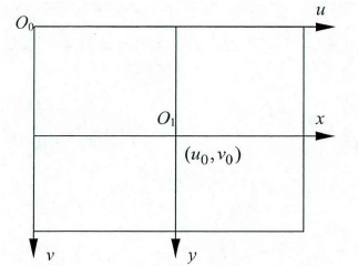
1. 像素坐标系
|  |
| :------------------------------------: |
| *像素坐标系与图像坐标系* |
- `$ (u,v) $`
- 单位:像素
- 原点:左上角
- 水平向右为u轴
- 竖直向下为v轴
2. 图像坐标系
- `$ (x,y) $`
- 单位:mm
- 原点:中心
- 水平向右为x轴
- 竖直向下为y轴
这里的变换关系
```[tex]
u = \frac{x}{dx} + u_0 \ , \ v = \frac{y}{dy} + v_0
```
(`$ dx $`为每个像素在横轴x上的尺寸,`$ dy $`为每个像素在纵轴y上的尺寸)
3. 相机坐标系
`$ (X_c,Y_c,Z_c) $`(在这一步还原了深度信息,其中`$ Z_c $`方向与光轴相同)
4. 世界坐标系
`$ (X_w,Y_w,Z_w) $`刚体变换,根据旋转矩阵**R**和平移向量**T**将相机坐标系旋转平移移动到用户定义下的世界坐标系。
队伍使用的空间位置解算的方式为solvePnp
- solvePnP(Perspectire-n-Point),n点透视问题,不仅指solvePnp,还可以有solveP3p
```C++
bool cv::solvePnP ( InputArray objectPoints,
InputArray imagePoints,
InputArray cameraMatrix,
InputArray distCoeffs,
OutputArray rvec,
OutputArray tvec,
bool useExtrinsicGuess = false,
int flags = SOLVEPNP_ITERATIVE
)
/**
@brief Finds an object pose from 3D-2D point correspondences.
简介 从3D-2D点对应中查找对象姿势。
This function returns the rotation and the translation vectors that transform a 3D point expressed in the object coordinate frame to the camera coordinate frame, using different methods:
此函数返回旋转和平移向量,这些向量使用不同的方法将对象坐标帧中表示的三维点转换为摄影机坐标帧:
- P3P methods (@ref SOLVEPNP_P3P, @ref SOLVEPNP_AP3P): need 4 input points to return a unique solution.
- P3P方法(@ref SOLVEPNP_P3P,@ref SOLVEPNP_AP3P):需要4个输入点才能返回唯一的解决方案。
- @ref SOLVEPNP_IPPE Input points must be >= 4 and object points must be coplanar.
- @ref SOLVEPNP_IPPE输入点必须大于等于4且对象点必须共面。
- @ref SOLVEPNP_IPPE_SQUARE Special case suitable for marker pose estimation.
Number of input points must be 4. Object points must be defined in the following order:
-@ref SOLVEPNP_IPPE_SQUARE适用于标记姿势估计的特殊情况。输入点的数量必须为4。必须按以下顺序定义对象点:
- point 0: [-squareLength / 2, squareLength / 2, 0]
- point 1: [ squareLength / 2, squareLength / 2, 0]
- point 2: [ squareLength / 2, -squareLength / 2, 0]
- point 3: [-squareLength / 2, -squareLength / 2, 0]
- for all the other flags, number of input points must be >= 4 and object points can be in any configuration.
对于所有其他标志,输入点的数量必须大于等于4,并且对象点可以是任何配置。
@param objectPoints Array of object points in the object coordinate space, Nx3 1-channel or 1xN/Nx1 3-channel, where N is the number of points. vector<Point3dcan be also passed here.
@param imagePoints Array of corresponding image points, Nx2 1-channel or 1xN/Nx1 2-channel, where N is the number of points. vector<Point2dcan be also passed here.
@param cameraMatrix Input camera intrinsic matrix cameramatrix .
@param distCoeffs Input vector of distortion coefficients. If the vector is NULL/empty, the zero distortion coefficients are assumed.
@param rvec Output rotation vector (see @ref Rodrigues ) that, together with tvec, brings points from the model coordinate system to the camera coordinate system.
@param tvec Output translation vector.
@param useExtrinsicGuess Parameter used for #SOLVEPNP_ITERATIVE. If true (1), the function uses the provided rvec and tvec values as initial approximations of the rotation and translation vectors, respectively, and further optimizes them.
@param flags Method for solving a PnP problem
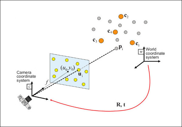
The function estimates the object pose given a set of object points, their corresponding image projections, as well as the camera intrinsic matrix and the distortion coefficients, see the figure below (more precisely, the X-axis of the camera frame is pointing to the right, the Y-axis downward and the Z-axis forward).
该函数估计给定一组对象点的对象姿势、其对应的图像投影以及相机固有矩阵和失真系数,请参见下图(更准确地说,相机帧的X轴指向右侧,Y轴向下,Z轴向前)。
*/
```
```[tex]
\texttt{cameraMatrix:} \quad
\bf{A} =
\left[ \begin{matrix}
f_x & 0 & c_x\\
0 & f_y & c_y\\
0 & 0 & 1
\end{matrix} \right]
```
```[tex]
\texttt{distCoeffs: }
(k_1, k_2, p_1, p_2, [,k_3[,k_4,k_5,k_6[,s_1,s_2,s_3,s_4[,\tau_x,\tau_y]]])
\text{of 4, 5, 8, 12 or 14 elements}
```
Points expressed in the world frame `$ \bf{X}_w $` are projected into the image plane `$ \left[ u, v \right] $`
using the perspective projection model `$ \Pi $` and the camera intrinsic parameters matrix `$ \bf{A} $`:
以世界帧`$ \bf{X_w} $` 表示的点投影到图像平面`$ \left[u,v\right] $`
使用透视投影模型`$ \Pi $`和相机内在参数矩阵`$ \bf{A} $`:
```[tex]
\begin{bmatrix}
u \\
v \\
1
\end{bmatrix} =
\bf{A} \hspace{0.1em} \Pi \hspace{0.2em} ^{c}\bf{T}_w
\begin{bmatrix}
X_{w} \\
Y_{w} \\
Z_{w} \\
1
\end{bmatrix}
```
```[tex]
\begin{bmatrix}
u \\
v \\
1
\end{bmatrix} =
\begin{bmatrix}
f_x & 0 & c_x \\
0 & f_y & c_y \\
0 & 0 & 1
\end{bmatrix}
\begin{bmatrix}
1 & 0 & 0 & 0 \\
0 & 1 & 0 & 0 \\
0 & 0 & 1 & 0
\end{bmatrix}
\begin{bmatrix}
r_{11} & r_{12} & r_{13} & t_x \\
r_{21} & r_{22} & r_{23} & t_y \\
r_{31} & r_{32} & r_{33} & t_z \\
0 & 0 & 0 & 1
\end{bmatrix}
\begin{bmatrix}
X_{w} \\
Y_{w} \\
Z_{w} \\
1
\end{bmatrix}
```
The estimated pose is thus the rotation (`rvec`) and the translation (`tvec`) vectors that allow transforming a 3D point expressed in the world frame into the camera frame:
因此,估计的姿势是旋转(`rvec`)和平移(`tvec`)向量,允许将世界帧中表示的3D点转换为相机帧:
```[tex]
\begin{bmatrix}
X_c \\
Y_c \\
Z_c \\
1
\end{bmatrix} =
\hspace{0.2em} ^{c}\bf{T}_w
\begin{bmatrix}
X_{w} \\
Y_{w} \\
Z_{w} \\
1
\end{bmatrix}
```
```[tex]
\begin{bmatrix}
X_c \\
Y_c \\
Z_c \\
1
\end{bmatrix} =
\begin{bmatrix}
r_{11} & r_{12} & r_{13} & t_x \\
r_{21} & r_{22} & r_{23} & t_y \\
r_{31} & r_{32} & r_{33} & t_z \\
0 & 0 & 0 & 1
\end{bmatrix}
\begin{bmatrix}
X_{w} \\
Y_{w} \\
Z_{w} \\
1
\end{bmatrix}
```
根据OpenCV函数 solvePnP() 指出,我们只需要提供**objectPoints**、**imagePoints**、**cameraMatrix**、**distCoeffs**就可以求出相机到物体的旋转向量 **rvecs**和平移向量 **tvecs**。而 **cameraMatrix**和**distCoeffs**在 [相机标定](##9. 相机标定) 中已经求出。**objectPoints**又是我们定义的,**imagePoints**是检测出来的像素坐标,故可以使用 *solvePnP*(输入点必须大于等于4且对象点必须共面)。
使用c++在此处应注意矩阵的**double**和**float**类型的差异。
用OpenCV的函数可以将**旋转矩阵**和**旋转向量**相互转化。
```cpp
void cv::Rodrigues ( InputArray src,
OutputArray dst,
OutputArray jacobian = noArray()
)
/**
@brief Converts a rotation matrix to a rotation vector or vice versa.
简介 将旋转矩阵转换为旋转向量,反之亦然。
@param src Input rotation vector (3x1 or 1x3) or rotation matrix (3x3).
@param dst Output rotation matrix (3x3) or rotation vector (3x1 or 1x3), respectively.
@param jacobian Optional output Jacobian matrix, 3x9 or 9x3, which is a matrix of partial derivatives of the output array components with respect to the input array components.
A rotation vector is a convenient and most compact representation of a rotation matrix (since any rotation matrix has just 3 degrees of freedom). The representation is used in the global 3D geometry optimization procedures like @ref calibrateCamera, @ref stereoCalibrate, or @ref solvePnP .
旋转向量是旋转矩阵最方便、最紧凑的表示形式(因为任何旋转矩阵只有3个自由度)。该表示用于全局三维几何优化过程,如@ref calibrateCamera、@ref stereoCalibrate或@ref solvePnP。
*/
```
```[tex]
\begin{array}{l} \theta \leftarrow norm(r) \\ r \leftarrow r/ \theta \\ R = \cos(\theta) I + (1- \cos{\theta} ) r r^T + \sin(\theta)
\left[ \begin{matrix}
0 & -r_z & r_y \\
r_z & 0 & -r_x \\
-r_y & r_x & 0
\end{matrix} \right]
\end{array}
```
```[tex]
\sin ( \theta )
\left[ \begin{matrix}
0 & -r_z & r_y \\
r_z & 0 & -r_x \\
-r_y & r_x & 0
\end{matrix} \right] = \frac{R - R^T}{2}
```
**世界坐标系**与**像素坐标系**相互转换:
../image/
|  |
| :------------------------------------------------------------------------------: |
| *世界坐标系与像素坐标系转换* |
有了**旋转矩阵**和**平移向量**,根据以下公式我们就可以实现**相机坐标系**到**世界坐标系**的转化:
```[tex]
\left[\begin{matrix}
X_c \\ Y_c \\ Z_c \\ 1
\end{matrix}\right]=
\left[\begin{matrix}
\bf{R} & \bf{T} \\ \bf{0} & 1
\end{matrix}\right]
\left[\begin{matrix}
X_w \\ Y_w \\ Z_w \\ 1
\end{matrix}\right]
```
```[tex]
\left[\begin{matrix}
X_c \\ Y_c \\ Z_c
\end{matrix}\right]=R
\left[\begin{matrix}
X_w \\ Y_w \\ Z_w
\end{matrix}\right] + t = [R \ t]
\left[\begin{matrix}
X_w \\ Y_w \\ Z_w \\1
\end{matrix}\right]
```
其中:**R** 为`$ 3 \times 3 $`旋转矩阵,**T**为`$ 3 \times 1 $`平移向量。`$ X_c $`为相机坐标系,`$ X_w $`为世界坐标系坐标。`$ Z_c $`方向为摄像头光轴方向,根据**R T**变换得到世界坐标系为用户在solvePnP中定义的世界坐标系。
```[tex]
\left[\begin{matrix}
x \\ y \\ 1
\end{matrix}\right]=
\left[\begin{array}{ccc}
f_x & 0 & u_0 \\
0 & f_y & v_0 \\
0 & 0 & 1
\end{array}\right]
\left[\begin{array}{cccc}
r_1 & r_2 & r_3 & t_1 \\
r_4 & r_5 & r_6 & t_2 \\
r_7 & r_8 & r_9 & t_3
\end{array}\right]
\left[\begin{matrix}
X \\ Y \\ Z \\ 1
\end{matrix}\right]
```
这里的`$ XYZ $`便是世界坐标`$ X_w $`,`$ Y_w $`,`$ Z_w $`。 得到的`$ (X_w,Y_w,Z_w) $`这个坐标本质是摄像机坐标系与表示三维场景结构的世界坐标系之间的绝对位姿关系(摄像机在用户定义下的世界坐标中的位姿)。进而得到目标俯仰角和偏航角。
